
Blog
Application of diamond wire saw for dismantling circular ring support systems in shopping mall basement construction
1. Project Overview
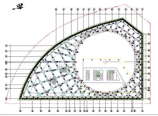
The project features a four-level basement with an excavation depth of approximately 20.30 meters and a foundation pit perimeter of about 323 meters. The designed service life of the foundation pit support structure is 24 months, calculated from the completion date of the support structure.
The support system adopts a pile-and-bracing scheme, with bored piles of 1.6 meters in diameter and a pile spacing of 1.8 meters. Four levels of reinforced concrete bracing are provided, consisting of circular ring braces and corner braces. All reinforced concrete beams and slabs are cast in C35 concrete.


2. Preconditions for Support Dismantling
- Before dismantling each level of internal supports, the lower structural slabs, the external basement walls, and the gaps between the piles and retaining walls must be fully backfilled, or the plain concrete belts must be completed. In addition, the concrete strength of the structural slabs and transfer beams, or the plain concrete belts, must reach at least 75% of the design strength before dismantling can commence.
- During dismantling, monitoring shall be strengthened. In the event of any abnormal situation, the design institute and the client must be notified immediately. Dismantling must be carried out by zones and in blocks, and coordinated handling shall be implemented jointly with all relevant parties. Support removal is permitted only when foundation pit monitoring data remains within normal limits.
- The dismantling sequence must be reviewed and approved by the design institute before execution.
- The contractor shall fully consider all possible situations before dismantling and prepare emergency response plans.
- Effective protective measures must be implemented for structural beams, slabs, basement exterior walls, and steel columns to prevent adverse impacts during dismantling.
- The unloading plan and forklift load on the slab must be calculated and verified before dismantling can proceed.
3. Zoning and Dismantling Sequence
3.1 Ring Beam Supports
The ring beam supports are divided into nine zones (A1–A9) for staged dismantling.
The dismantling sequence is as follows:
A6 → A3 → A8 → A4 → A9 → A7 → A5 → A1 → A2

3.2 Main Supports
The foundation pit is divided into four major zones (A–D).
The dismantling sequence is as follows:
A → B → C → D

4. Support Dismantling Construction
4.1 Construction Approach
The dismantling of internal supports in this project is divided into three categories: main supports, ring beams, and access bridges.
- Ring Beam Dismantling
The dismantling of the ring beams follows the principle of “remove sections with smaller stress first, followed by those with higher stress”.- The sequence is as follows: first dismantle Section A6, then dismantle other sections symmetrically, and finally dismantle Sections A1 and A2.
- Main Support Dismantling
After completing the ring beam dismantling, the main supports will be dismantled according to the designated zoning sequence.
During dismantling, the internal forces of the foundation pit support structure will change significantly. In order to protect the safety of the foundation pit and its surrounding environment, it is essential to avoid excessive stress release after support removal. Therefore, the following principles must be observed:- A. Overall dismantling sequence of support beams (according to progress and construction flow):
- First dismantle the connecting beams of the corner supports.
- Then dismantle the corner support beams.
- Next, dismantle the opposing supports.
- Finally, dismantle the waist beams.
- B. Based on the basement structural top slab elevation and the relative position of the support beam bottom:
- (1) For detailed work: first dismantle the connecting beams between support beams, then dismantle the outer support beams.
- For single support beams, dismantling shall proceed from the middle toward both ends.
- A. Overall dismantling sequence of support beams (according to progress and construction flow):
- Access Bridge Dismantling
After the removal of soil in the inner pit (“pit-in-pit”), the access bridges shall be dismantled.
4.2 Construction Arrangement
This section is divided into sequential work zones. Each construction zone shall follow the same procedures:
- Installation of special steel saddles (for dismantling the first to fourth levels of internal supports).
- Layout and marking of cutting lines according to support beam conditions.
- Two-stage unloading.
- Cutting of support beams.
- Horizontal movement of dismantled concrete blocks.
- Hoisting of concrete blocks.
- Loading and external transportation of dismantled blocks.
- Off-site crushing of concrete blocks and recovery of reinforcement steel.
4.3 Construction Workflow
The dismantling process shall follow the workflow below:
Completion of transfer support system → Cutting line marking → Installation and fixation of guide pulleys → Installation and fixation of the wire saw machine → Mounting of the diamond wire rope → Connection of operation systems → Setup of protective barriers → Cutting of internal support beams with diamond wire saw → Hoisting and external transportation of dismantled blocks (pneumatic breaker if needed).
5. Principle of Diamond Wire Saw Dismantling and Equipment Selection
5.1 Principle of Diamond Wire Saw Cutting
The Diamond Wire Saw dismantling method uses a diamond-embedded wire rope, driven by a hydraulic motor, to move at high speed around the cutting surface, grinding and cutting the target structure.
Because single-crystal diamonds are used as the abrasive material, this method can efficiently cut through hard objects such as stone and reinforced concrete.
The cutting process is powered by a hydraulic pump station. At the initial stage, the diamond wire rope is wrapped and fixed around the reinforced concrete support beam to be cut. The hydraulic pump station then drives the cylinder mounted on the saw frame. During cutting, the cylinder continuously moves along the saw frame, and once it reaches a certain position, the targeted concrete block is nearly completely cut.
Key features of the process:
- Safe and convenient operation.
- Minimal vibration and low noise.
- The cut structure can be separated with almost no disturbance to its surroundings.
- The diamond wire rope operates at high speed and must be cooled with water during cutting, which also removes abrasive debris.
- Normal cutting time for one concrete cross-section is approximately 30 minutes, depending on the beam size.
5.2 Equipment Selection
The primary cutting equipment selected for this project includes:
- Diamond Wire Saw (FeILI Wire Saw Machine series), combined with drilling machines for support cutting.
Main performance parameters of the Diamond Wire Saw:
- Pure cutting speed: 30–50 minutes per cross-section square meter
- Installation time: 20–40 minutes per setup
Diamond Wire Saw
- Equipped with diamond wire saw for reinforced concrete cutting.
Drilling Machine:
- Pure cutting speed: 1.2 hours per cross-section square meter
- Installation time: 5 minutes per setup


6. Temporary Support System Installation
6.1 Existing Formwork System
During the dismantling of internal supports, the existing formwork system beneath the supports is retained and utilized as the back-propping system for the basement roof slab. Therefore, no additional back-propping construction is required.
Before dismantling begins, the original support system must be carefully inspected and accepted.
6.2 Temporary Support System Installation
During dismantling of the internal support beams, the self-weight of the supports and other loads are transferred to the lower slab through wooden pads or steel saddles, and further transmitted down to the foundation slab via the basement slab support system.
According to the excavation support drawings and structural drawings:
- The bottom of the fourth-level internal support beam is 2.75 m above the -5F foundation slab surface.
- The bottom of the third-level internal support beam is 3.36 m above the -4F foundation slab surface.
- The bottom of the first-level internal support beam is 3.26 m above the -2F top slab surface.
For dismantling, assembled steel saddles are adopted as the temporary support system for these beams.
For other positions with a height of 1.36 m, A-frame type steel saddles are adopted as the temporary support system.
When dismantling the internal supports, saddles are installed beneath the support beams to ensure that each cut section of the support beam is supported by a saddle.
When the corner reinforcement bars on both sides of the cut are removed, one steel saddle is sufficient to back-prop each beam segment.
(To improve the overturning resistance of the assembled saddles, one longitudinal rebar is retained on each side of the cutting section, increasing the stability of the assembly.)
⚠️ Since significant safety risks exist during cutting operations, a dedicated safety supervisor must be present throughout the process.
Technical Parameters for the Second-Level Support Saddles
- Saddle height: 1.36 m
- Upper chord length: 1.0 m
- Lower chord length: 1.0 m
- Vertical member length: 1.7 m
- Bracing rod length: 0.6 m
Requirements for High-Level Saddles (>2.0 m)
Based on design drawings:
- The fourth-level support beam bottom is 2.75 m above the slab.
- The third-level support beam bottom is 3.36 m above the slab.
- The first-level support beam bottom is 3.26 m above the slab.
For heights above 2.0 m, assembled square steel saddles shall be used for support. The spacing between saddles is determined by the block cutting size, ensuring that each cut segment of the support beam rests on saddle support.
Installation Process for Assembled Square Steel Saddles
- The vertical columns of the assembled saddles are fabricated from square steel. Before use, the components are bolted together in advance according to the required dimensions. The work surface under the beam to be cut must be cleaned before saddle installation.
- Saddles are transported to the beam position by forklift. After installation, if the gap between the saddle top and the beam bottom is greater than 15 cm but less than 25 cm, the gap must be fully filled and wedged tightly with adjustable jacks, timber, and planks. If the gap is less than 15 cm, it may be filled directly with timber wedges.
- During cutting, the main rebars on both sides of the beam are temporarily retained (not cut initially). The auxiliary support provided by these rebars reduces the load on the special saddles and prevents beam overturning after segment separation. When the blocks are ready for forklift transport, the reserved rebars are cut off using a plasma cutter, allowing safe removal.


7. Cutting Construction Process and Procedures
7.1 Construction Process
- Connect onsite power supply and water supply.
- Mark block cutting lines on the support beams and ring beams.
- Use a drilling machine to drill through-holes (diameter ≥108 mm) at the intersection points of cutting lines on the ring beams, close to the wall, for threading the diamond chain.
- Place the cutting machine on the ring beam or support beam and connect it properly to the power and water supply.
- Thread the diamond chain through the holes, connect the joints using a hydraulic clamp, and ensure proper assembly.
- Open the water supply, adjust the water flow, and tighten the chain using the controller.
- The pin dimension of the drilling platform must be fixed, with the distance from the cutting line to the pin center being 42 cm.
- Calculation of diamond wire length:
- Formula:
Total length L = L1 + L2 + 0.6 m
L1 = Perimeter of the component – 0.8 m (width of saw system)
L2 = Length reserved for protruding parts + 0.5 m - Example calculation:
L1 = 1.0 m + 0.8 m + 1.3 m + 0.6 m + 2.2 m – 0.8 m = 5.1 m
L2 = 2.4 m (chain deformation allowance)
L = 5.1 + 2.4 + 0.6 = 8.1 m
- Formula:
- Cutting sequence of supports: In principle, cut from the middle first, then the two sides. The first lifted block should be cut with an inclined edge to facilitate hoisting.
7.2 Support Beam Cutting Method
- Before cutting, a temporary support system must be installed to ensure safety.
- To prevent concrete blocks from overturning or becoming unstable during cutting, the two longitudinal corner rebars on the top side of the beam must be retained temporarily (see diagram).
- Specific method: At 100 mm from the vertical edge on the upper side of the support beam, use a pneumatic breaker to create notches while preserving one corner rebar on each side of the beam top.
- The diamond chain is passed below these rebars, ensuring the rebars remain intact during cutting.
- When cutting the beam, the reserved rebars on both sides are not cut initially. After the beam block has been cut and is stabilized by forklift or tower crane lifting, the reserved corner rebars are cut using a welding torch or plasma cutter, ensuring safety during block removal.


7.3 Waist Beam Cutting Construction Method
- Using a drilling machine, drill through-holes with a diameter of no less than 63mm at the junctions of the waist beam cutting lines and the protective piles or diaphragm walls for threading the diamond wire (or use a pneumatic drill for drilling). If the construction team confirms in advance, the wire holes can be pre-embedded during the pouring of concrete supports (the standard for pre-embedding is a 25mm diameter PVC pipe, arranged at 1000mm intervals along the junctions of the protective beams and piles). Pre-embedding can save both time and cost.
- On the waist beam, based on the length of the straight sections, thread the diamond cutting wire through the drilled holes at certain intervals. Use a wire saw cutting machine to cut the junction between the waist beam and the protective structure. After cutting a certain length on the inner side of the waist beam (cutting length not exceeding 10m at the junction with the diaphragm wall, and not exceeding 5m at the junction with the protective piles), perform block-by-block cutting perpendicular to the waist beam. The first block should be cut into a V-shape to ensure smooth removal of the concrete block.


7.4 Ring Support Cutting Construction Method
- Before cutting, set up the support system and complete temporary support work.
- Drill holes using a pneumatic drill 100mm from the vertical edge of the beam side, leaving the two top corner main rebars of the support beam intact, and thread the chain through the rebars (ensuring no damage to the rebars). Do not cut the upper corner rebars on both sides of the beam during cutting; cut them only before lifting to ensure construction safety.
- Because the cross-section of the ring-shaped support beam is too large, to control block weight and component lifting dimensions, the ring support is cut first by dividing the middle section, then by segmental cutting. The specific construction method is as follows:
(1) Mark the plane centerline of the ring support and the block cutting lines, and drill wire-passing holes at the intersection points using a water drill.
(2) Use an electric wire saw cutting machine to first perform longitudinal separation cutting, followed by block cutting.
7.5 Principles for Dividing Support Beams into Blocks
- The reinforced concrete blocks from the main supports must not exceed 8 tons after cutting, and the blocks from the trestle supports must not exceed 10 tons to ensure safety before lifting.
- Reinforced concrete blocks should remain stable and reliable during the lifting process.
- The size of reinforced concrete blocks should consider the crane selection and its lifting stability and moment.
- Reinforced concrete blocks should be minimized as much as possible; the total cutting volume may increase, so machinery should be adjusted according to construction progress to achieve the fastest construction speed.
- Before cutting the support beams, accurate layout should be performed so that the cut concrete blocks roughly match the theoretical calculation values, avoiding overload during lifting and potential safety hazards.

8. Lifting of Concrete Blocks (Slabs)
8.1 Overview of the Lifting Plan
For each main support, the removal process combines cutting and lifting. The weight of the cut support concrete blocks is controlled within 8 tons. Blocks are transported to the lifting point using a 10-ton forklift, then lifted using an on-site mobile crane.
Considering the site conditions, the design excavation load, and the crane performance parameters, the heaviest lifted object is 10 tons, though most blocks are 6–8 tons. For the trestle section, the lifting distance is approximately 38m, with blocks weighing around 8 tons, so a 220-ton mobile crane is selected. Since the ring supports are removed as a whole, three lifting points are designed.
The mobile cranes are positioned on the east, south, and northeast sides of the excavation pit, with the crane center located 5m from the pit edge for lifting operations. The lifting distance is 38m. For safety, the main supports are limited to 8 tons per block.
For the trestle section: a 220-ton crane is positioned about 40m on the east side of the excavation pit, lifting blocks of 8 tons each for 2/3 of the section; then the 220-ton crane is moved to the south side of the pit, also about 40m, lifting blocks of 8 tons each. Blocks beyond the effective radius are transported to the pit edge using a 10-ton forklift, then lifted with the mobile crane.
8.2 Forklift Travel Route
The internal support beam concrete blocks are transported using a 10-ton diesel mechanical forklift, model Helih CPCD100.

Considering the limitations of horizontal transport equipment and floor slab load capacity, the forklift travel routes must be properly planned on the floor slabs. All forklifts are prohibited from operating outside these designated routes. All formwork supports beneath the travel routes, especially at post-cast strip locations, must not be removed. Steel plates with dimensions of 3m × 1.5m × 10mm should be laid along the travel routes and turning areas, and the plates must be installed continuously.

First, use the forklift to partially transfer the cut support beams from the interior outward to the designated concrete block lifting area, and then lift them out of the excavation pit using the mobile crane.

- After the beams are cut block by block and rested on the temporary supports, use forklifts to horizontally transport them to the nearest crane lifting points. Lift the cut blocks out of the excavation pit using the crane. During the removal of each area, dismantle the supports segment by segment in a clockwise sequence.
- Before forklift operation, steel plates must be laid between the sections of internal support being removed and the concrete blocks. The forklift should travel only on the steel plate path for that section. After the support beams in that section are removed, move the steel plate path to the next section and continue dismantling the next segment clockwise.
The forklift travel path on the floor must be checked and verified through calculation to ensure the original formwork support system can meet the load requirements. Specific calculations are detailed in the calculation report.
- Forklift routes must avoid finished building rebars and post-cast strips. Forklifts with loads are prohibited from passing over post-cast strips. If an empty forklift cannot avoid a post-cast strip, a 2cm thick reinforced steel plate should be laid over it.
8.3 Lifting
- The weight of the removed concrete blocks should be controlled according to the crane’s slewing radius requirements. Since the beam cross-sections are regular, the cut concrete blocks will have the same shape and center of gravity. Before lifting, calculate the center of gravity to determine the lifting points.
- During beam lifting, maintain a uniform speed and ensure the component is stable. When lowering the concrete block, it must be done slowly and carefully.
- This project uses a single crane with two-point lifting. The mechanical slewing radius is controlled between approximately 8m and 14.6m.
- Select two lifting points according to the specific location of the support beam being lifted.
- Prepare all work in advance. Direct the crane to move to the lifting position (lifting points located 50cm from both ends). Install lifting chains and hooks on the reinforced concrete blocks, check the installation of the crane lifting chains and the center of gravity, then begin simultaneous lifting. A schematic diagram of the lifting operation is shown below:

8.4 External Transport
During the cutting operations, the cut concrete blocks are transported horizontally using a 10-ton forklift, lifted directly by the crane, and then transported offsite for crushing. The specific timing of external transport depends on the lifting schedule.
- The disposal site is selected to avoid damaging existing water systems and facilities, and to prevent pollution of local residents’ living and working areas. From a construction perspective, the site should be convenient for traffic, along the shortest or optimal route. The final location is determined based on a comprehensive review of previous cooperation sites.
- The transport route should be a combined route that ensures smooth vehicle traffic and allows for timely and efficient turnover.
9. Removal of Steel Columns and Support Plates
9.1 Steel Column Removal Method
Since the basement slab has been completed and the steel columns are heavy, a segmented removal method is adopted. The steel columns are cut in segments using an oxygen-acetylene gas torch, with each segment not exceeding 3m in length. Segments within the tower crane’s coverage are lifted out through preformed holes in the slab. Segments outside the crane’s coverage are lifted with a forklift, with each segment not exceeding 2m, transported via the garage ramp to the mobile crane lifting point, and then lifted out.
When cutting and segmenting steel columns, scaffolding must be used. Set up scaffolding platforms and stabilize the columns during cutting to prevent tipping and ensure safety.
During construction, welding, gas cutting, and other open-flame operations are required. Obtain approval for open-flame work before starting and provide necessary fire-fighting equipment.
Concrete blocks at the connection between support beams and steel columns, which cannot be fully cut by the cutting machine, should be removed using a type-120 breaker. The debris is collected, cleaned, and transported offsite.

10. Acceptance of Support Removal and Replacement
10.1 Acceptance of Support Replacement
Acceptance is conducted for replacement beams and plates, as well as I-beams in segmented positions. For replacement plates, first check the foundation elevation. If there is backfill at the bottom of the pit, verify the compaction of the backfill. During installation of replacement plates, the supervisor and other responsible personnel must be on-site.
Random concrete test blocks should be cast, with an extra set for testing. After 7 days, the compressive strength must reach 75%, and the report must be received before proceeding with removal operations.
Replacement beam construction must strictly follow the drawings. During construction of the B2 floor, accurately mark the external wall lines and reserved beam positions. Drill holes in protective piles for rebar anchoring, ensuring depth meets relevant standards. Supervisors are responsible for inspecting rebar depth and installation, including pull-out tests.
Check the position of support beams, including cross-sectional dimensions, rebar specifications, spacing, and clearance. If all conditions are met, concrete can be poured. Random test blocks should again be taken, and removal operations can begin after the strength reaches 75%.
10.2 Acceptance Items
Once the replacement support construction is complete and meets removal conditions, proceed with support removal operations.
Support removal must strictly follow the plan. Key nodes require inspection, with the on-site supervisor and monitoring unit present.
Before construction, all machinery—cutting saws, breakers, forklifts, cranes—must have valid certificates and relevant inspection data. Large machinery must be registered, and all personnel must receive on-site safety education and briefings.
Before removal, in addition to machinery inspection, special attention should be given to steel stirrups and other support conditions. For the first support working surface on the B2 slab, check whether the formwork supports below have been removed or loosened, and reinforce if necessary, especially along forklift travel paths.
Before unloading support beams, each segment should be checked by the site supervisor to control the size and weight of concrete blocks. Removed concrete blocks must be lifted immediately and not stored on top of the garage slab or at the pit edge.
11. Finished Structure Protection
11.1 Protection of Structural Slabs
- When cutting internal support beams, cut blocks must not fall on the structural slabs. They must be temporarily supported by the support system, then lifted directly by forklift to the pit edge.
- After forklift transport to the pit edge, cut blocks must not be placed directly on the structural slab. Place three stacked rows of timber blocks at the lifting point, and position the cut blocks on top.
- Forklifts must avoid driving over post-cast strips while carrying loads. Empty forklifts may temporarily travel over post-cast strips if 20mm thick steel plates are laid.
11.2 Protection of Steel Columns and Other Support Beams
- Steel columns are integrally cast with the floor slab, providing an additional protective layer.
- Forklifts must not collide with steel columns while traveling on the slab.
- When lifting cut blocks with a mobile crane, start lifting slowly. After clearing the height of the support structure, rotate the crane to avoid collisions with steel columns and other support beams.